RF Considerations for Skype for Business

A while back I provided a client with a detailed design for a wireless solution and at the time a high focus was placed on the clients Skype for Business deployment. During my research I found Skype for Business over Aruba – Validated Reference Design and found the RF considerations below that can be used for any voice over  wireless LAN (VoWLAN) solution. This should be helpful to site survey engineers or engineers troubleshooting voice issues.

  • Power Settings – Transmit power values are 3, 6, 9, 12, 15, 18, 21, 24, 27, 30, 33, and 127 dbm. Consistent power levels will result in higher data rates. Minimum and maximum AP transmit power difference should not be more than two steps apart. For example, if the minimum transmit power is 9 dbm then the maximum transmit power should not exceed 15 dbm. AP power setting should use low to moderate power. For example, in a high density AP deployment set the minimum/maximum power should be 9 -12 dbm for 2.4 GHz and 12 -18 dbm for 5 GHz.
  • Disable lower transmit data rates – If there are no 11b clients in the network, disable lower rates 1 – 11 Mbps.
  • Set supported beacon rate to more than 12 Mbps – Beacons that are transmitted at the lowest basic rate, such as 1 Mbps, can consume a considerable amount of air time. Beacon rates should be set higher than 12 Mbps to avoid unnecessary consumption of bandwidth.
  • Minimum RF signal (Received Signal Strength Indication (RSSI)) levels of -65 dbm in 2.4 and 5 GHz.
  • Minimum Signal to Noise Ratio (SNR) of 25 dB – Higher signal level and high SNR are the indicators of a superior RF environment and will improve client transmission rates.
  • Mitigate interference sources, such as microwave ovens, distributed antenna systems, and game consoles.
  • Use 20 MHz channel bandwidth on 2.4 GHz.
  • Use 40 MHz or less channel bandwidth on 5 GHz – It is recommended that high density deployments use 40 MHz or less channel bandwidth to reduce adjacent and co-channel interference. Using 80 MHz channel bandwidth in high density AP deployments may result in adjacent or co-channel interference.
RF Considerations for Skype for Business

Mist: Personal WLAN

This is quite a nice feature from Mist that allow the secure on-boarding and segmentation of users and wireless devices, especially Internet-of-Things devices that do not have 802.1x support. Usually you would have to separate users through the use of separate SSID’s with each SSID having its own personal passphrase and in some cases place them on separate VLANs and subnets and add to that the ACLs required for each SSID.

Capture2

Mist now have “patent-pending” personal WLAN technology, which means users and devices will use a common SSID but different personalised pre-shared keys (PSK) across all access points. Thus, if a group of devices share the same PSK they share the same resources and if you don’t belong to that controlled group you won’t be able to access these devices or services. Users can create their own private keys that can then be applied to the devices of their choosing and shared within a controlled group.

Capture1

This will stop the need for smaller wireless deployments to invest in expensive segmentation such as radius servers to provide authentication, authorisation and accounting (AAA). It also limit the number of SSIDs, which will help to keep the wireless spectrum utilisation efficient and clean.

As per Mist this will be perfect for environments where users need private access to shared devices, such as hotels, retail stores, malls, public venues and school dormitory rooms.

Mist: Personal WLAN

WPA3

At the beginning of 2018 the Wi-Fi Alliance announced new security enhancements for Wi-Fi Protected Access (WPA). WPA3 has the following enhancements:

  • Device Provisioning Protocol (DPP) –DPP enables new devices that do not have a rich user interface to be added to the network via a smartphone or tablet of a user already authenticated, think Internet of Things (IOT). DPP enables the provisioning (on- and off-boarding) of any type of devices while maintaining security.
  • Opportunistic Wireless Encryption (OWE) – OWE derives an encryption key between an access point (AP) and a client to what we see as an open SSID and will prevent eavesdropping attacks. Just remember, OWE adds encryption but not authentication.
  • Suite-B – WPA3 introduces 256-bit encryption which adopts stronger cryptographic algorithms defined by the US Government. Once available, all wireless deployments will benefit from these capabilities. 
  • Simultaneous Authentication of Equals (SAE) – SAE is for customers that use insecure passwords, by adding another layer of security with the introduction of a secure handshake. SAE is a secure key establishment protocol between devices, to provide stronger protection for users against password guessing attempts by third parties. The result of the protocol is a cryptographically strong shared secret for securing communication. SAE is resistant to passive attacks, active attacks and dictionary attacks.
WPA3

Quick and Easy Hotspot Solution

Solution Overview

To provide a Hotspot WiFi solution that provide internet access through Cisco Identity Services Engine (ISE) by:

  • Ensuring all guests are bandwidth limited to 5 Mbps during Internet access.
  • Guests are able to connect during office hours only to the Hotspot SSID.
  • Guests are provided access after accepting terms and conditions from the Hotspot portal provided.
  • The Hotspot portal is provided through HTTPS.
  • Redirection is enabled on WLCs to direct guests to the Hotspot portal automatically.
  • Portal certificates are installed to secure the portal and enable user devices to trust the patient portal.

In this solution, the guest connect to the network with a wireless connection. Cisco ISE, using the Hotspot Guest portal, allow patient devices to connect to a private network by accepting terms and conditions.

The following is an outline of the subsequent Cisco ISE process:

  • The network access device (NAD) sends a redirect to the Hotspot Guest portal.
  • If the MAC address of the guest device is not in any endpoint identity group or is not marked with an Acceptable Use Policy (AUP) accepted attribute set to true, Cisco ISE responds with a URL redirection specified in an authorisation profile.
  • The URL redirection presents the patient with an AUP page when the guest attempts to access any URL.
  • If the guest accepts the AUP, the endpoint associated with their device MAC address is assigned to the configured endpoint identity group. This endpoint is now marked with an AUP accepted attribute set to true, to track the guest acceptance of the AUP.
  • If the patient does not accept the AUP or if an error occurs, for instance, while creating or updating the endpoint, an error message displays.
  • After the endpoint is created or updated, a Change of Authorization (CoA) termination is sent to the NAD.
  • After the CoA, the NAD re-authenticates the patient connection with a new MAC Auth Bypass (MAB) request. The new authentication finds the endpoint with its associated endpoint identity group, and returns the configured access to the NAD.

Based on the Hotspot Guest portal configuration, the guest is directed to the business unit URL from where they are connecting.

flow

Wireless LAN Controller

WLAN Configuration

Create a new SSID on the WLC by providing the following configuration under       WLANs > WLANs:

Setting Configuration
Profile Hotspot_Profile
SSID Hotspot
Interface Hotspot_interface
Layer 2 Security None
Mac Filtering Enabled
Layer 3 Security None
Captive Network Assistant Bypass Disable
AAA Servers – Authentication Servers Enabled

IP:x.x.x.x (Cisco ISE PSN), Port:1812

AAA Servers – Accounting Servers Enabled

IP:x.x.x.x (Cisco ISE PSN), Port:1813

QOS Silver (best effort)
QOS Application Visibility Enabled
Average Data Rate Downstream:5000 Upstream:5000
Burst Data Rate Downstream:5000 Upstream:5000
Average Real-Time Rate Downstream:5000 Upstream:5000
Burst Real-Time Rate Downstream:5000 Upstream:5000
Allow AAA Override Enabled
DHCP Addr. Assignment Enabled
NAC State ISE NAC

Interface Configuration

The following VLAN interface parameters must be configured on the WLC to provide guest devices an ip-address under CONTROLLER > Interfaces:

Setting
Interface Name
VLAN Identifier
Netmask
Gateway
IP Address
DHCP Server

AAA Configuration

The Cisco ISE Policy Service Nodes (PSN) must be added to the WLCs as radius servers to provide AAA functions. Below is a screenshot example:

AAA1

The ‘Auth Called Station ID Type’ were updated to indicate ‘AP Name:SSID’. This enables policies within Cisco ISE to look up the AP name onto which a patient connected to determine which hotspot portal are provided to that guest.

AAA2

Access Control Lists

Two access control lists (ACL) were created in this case and are used within policy profiles when deploying the new Hotspot WiFi solution. These are:

  • Guest_wifi_redirect – This ACL will only allow DNS services and access to the PSN nodes and deny all other traffic. This ACL will enable guest to be redirected to the Hotspot WiFi portal to accept terms and conditions after connecting to the SSID.
  • Guest_permit – This ACL permits all traffic a guest is allowed or denied after accepting terms and conditions.

Cisco Identity Services Engine

Ensure the Cisco WLC is added as a NAD (Network Access Device) before completing the rest of the configuration.

Identity Group

Identity Groups are a collection of individual endpoints that share a common set of privileges that allow them to access a specific set of Cisco ISE services and functionality.

In this case, guest endpoints (MAC addresses) are placed in an Identity Group  after the guests accepts the terms and conditions on the portal. These endpoints are purged after one day. This allows the creation of a policy that will allow guest endpoints in this group access to the network.

This group can be created under Administration > Identity Management > Groups > Endpoint Identity Groups. For this example we will call it HotspotEndpoints.

The purge policy to remove all endpoints daily from the HotspotEndpoints identity group can be created under Administration > Identity Management > Settings > Endpoint Purge.

Wildcard Certificate

In this example a wildcard certificate was used to secure the portal. A wildcard certificate uses a wildcard notation (an asterisk and period before the domain name) and allows the certificate to be shared across multiple hosts in an organisation. The wildcard notation of *.customerdomain.com (for example) must be imported to the Cisco ISE nodes as well as the root and intermediate certificates for the wildcard certificate within the trusted certificate store.

These certificates can be purchased from a public Certificate Authority (CA). Best practise would be to generate a certificate signing request (CSR) and upload it to the CA when purchasing the certificate.

This link will be helpful.

Time and Date Conditions

Time and date conditions let you set or limit permission to access Cisco ISE system resources to specific times and days as desired by the attribute settings you make.

Below is the ‘Time and Date Condition’ applied to my authorisation policies.

T&D

Portal Configuration

Cisco ISE has a default Hotspot Guest Portal that can be duplicated and customised to fit your company requirements. The diagram below indicates how to duplicate a portal.

PortalDuplicate

Within the ‘Hotspot Guest Portal’ the following is a requirement:

  • Under Portal Settings > Certificate group tag select the group your wildcard certificate belongs to. Most likely ‘Default Portal Certificate Group’.
  • Under Portal Settings > Endpoint Identity Group select the identity group configured earlier.
  • To include an acceptable use policy (AUP) go to ‘Acceptable Use Policy (AUP) Page Settings’ and select ‘Include an AUP page’.
  • Within the ‘Authentication Success Settings’ configure the URL specific to the business units home webpage.

The diagram below shows where logos, banners, terms and conditions specific to the business unit and a colour scheme can be updated.

PortalSettings

Below is an example of a hotspot portal.

Portal

Authorisation Profiles

Authorisation policies associate rules with specific user and group identities to create the corresponding profiles. Whenever these rules match the configured attributes, the corresponding authorisation profile that grants permission is returned by the policy and network access is authorised accordingly.

Two authorisation profiles was created for this example. The first authorisation profile will ensure when a guest endpoint connect to the SSID they are redirected to the correct portal and the ‘Guest WiFi redirect’ ACL are pushed down to the endpoint.

There will also be an authorisation profile that will grant guest endpoints access to the internet and push down ACL ‘Guest Permit’ to the endpoints.

To create these authorisation profiles go to Policy > Policy Elements > Results > Authorization > Authorization Profiles.

Authorisation Profile

ACL Redirect Portal Authorisation Policy Portal FQDN
Guest_WiFi_Redirect Guest_wifi_redirect Hotspot Portal Guest_WiFi_Redirect hotspot.customerdomain.com (Make sure there is a DNS entry)
Guest_WiFi_Permit Guest_permit NA Guest_WiFi_Permit NA

Policy Sets

Policy sets enable you to logically group authentication and authorisation policies within the same set.

For this example a policy set was created specifically for the Hotspot WiFi solution. All authentication and authorisation policies for this solution are contained within this policy set. For endpoints to be allowed access within this policy set patients need to connect to the Hotspot SSID which has been configured as WLAN ID 4 on the WLC.

Create the policy set under Policy > Policy Sets and in my case the condition is Airespace:Airespace-Wlan-Id EQUALS 4.

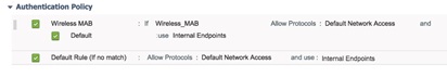
Authentication policies define the protocols that Cisco ISE uses to communicate with the network devices, and the identity sources that is used for authentication. The authentication policy within the patient policy set allow all devices connecting through a wireless connection (as long as it connected to WLAN ID 4). Below is the configuration for my example.

Auth

Authorisation policies can contain conditional requirements that combine one or more identity groups using a compound condition that includes authorisation checks that can return one or more authorisation profile. This example has two authorisation policies as per the table below:

Authorisation Policy Condition Authorisation Profile
Guest_WiFi_Redirect Wireless_MAB

Guest endpoint must connect to an AP which name contains XXXXX (Make sure all APs in your deployment has those characters in it).

Guest can only connect week days during office hours.

Guest_WiFi_Redirect
Guest_WiFi_Permit Wireless_MAB

Guest endpoint device must be in the ‘HotspotEndpoints’ identity group.

Patient can only connect week days during office hours.

Guest_WiFi_Permit
Quick and Easy Hotspot Solution

Channels and Maximum Power Settings for Cisco 3700

The Tx Power Level Assignment for each AP shows its current power level assignment in a numbering system that starts with 1 and ends with 8. The number 1 indicates the AP is on full power and the higher the number goes less power are transmitted.

That number (1-8) can be converted to dBm or mW to show the AP’s actual power output by using this command ‘show ap config 802.11a’. It is here where you might notice the power level of APs all on power level 1 might not be transmitting the same dBm or mW.

The reason for this is the UNII band the AP is on for example below is an extraction of the ‘show ap config 802.11a’ command for three APs. All three AP’s were configured exactly the same except for Dynamic Channel Assignment (DCA) which put them on three different UNII bands.

UNII-1

Tx Power
Num Of Supported Power Levels …………. 3
Tx Power Level 1 …………………….. 8 dBm
Tx Power Level 2 …………………….. 5 dBm
Tx Power Level 3 …………………….. 2 dBm
Tx Power Configuration ……………….. AUTOMATIC
Current Tx Power Level ……………….. 1
Tx Power Assigned By …………………. DTPC
Phy OFDM parameters
Configuration ……………………….. AUTOMATIC
Current Channel ……………………… 36
Channel Assigned By ………………….. DCA

UNII-2Ext

Tx Power
Num Of Supported Power Levels …………. 5
Tx Power Level 1 …………………….. 16 dBm
Tx Power Level 2 …………………….. 13 dBm
Tx Power Level 3 …………………….. 10 dBm
Tx Power Level 4 …………………….. 7 dBm
Tx Power Level 5 …………………….. 4 dBm
Tx Power Configuration ……………….. AUTOMATIC
Current Tx Power Level ……………….. 1
Tx Power Assigned By …………………. DTPC
Phy OFDM parameters
Configuration ……………………….. AUTOMATIC
Current Channel ……………………… 100
Channel Assigned By ………………….. DCA

UNII-3

Tx Power
Num Of Supported Power Levels …………. 8
Tx Power Level 1 …………………….. 23 dBm
Tx Power Level 2 …………………….. 20 dBm
Tx Power Level 3 …………………….. 17 dBm
Tx Power Level 4 …………………….. 14 dBm
Tx Power Level 5 …………………….. 11 dBm
Tx Power Level 6 …………………….. 8 dBm
Tx Power Level 7 …………………….. 5 dBm
Tx Power Level 8 …………………….. 2 dBm
Tx Power Configuration ……………….. AUTOMATIC
Current Tx Power Level ……………….. 1
Tx Power Assigned By …………………. DTPC
Phy OFDM parameters
Configuration ……………………….. AUTOMATIC
Current Channel ……………………… 149
Channel Assigned By ………………….. DCA

All three APs indicate Power Level 1 on the Wireless LAN Controller but their actual power transmit power is:
AP1 = 8dBm
AP2 = 16dBm
AP3 = 23dBm

With this information available you might want to disable certain UNII-bands as the power output is not enough for the environment the APs are in.

Below is the path to get to the Cisco provided spreadsheet indicating what the power setting will be for your regulatory domain using certain antennas, configuration settings and certain UNII-bands.

http://www.cisco.com/c/en/us/support/wireless/aironet-3700i-access-point/model.html

Under Install and Upgrade Guides click on Detailed Channels and Maximum Power Settings for Cisco 3702e and 3702i Series Access Points.

 Have fun.

Channels and Maximum Power Settings for Cisco 3700

Cisco Notification Alert

Title

Cisco Wireless LAN Controller Unauthorized Access Vulnerability

Link

http://tools.cisco.com/security/center/content/CiscoSecurityAdvisory/cisco-sa-20160113-wlc

Description

Devices running Cisco Wireless LAN Controller (WLC) software versions 7.6.120.0 or later, 8.0 or later, or 8.1 or later contain an unauthorized access vulnerability that could allow an unauthenticated, remote attacker to modify the configuration of the device.

An attacker who can connect to an affected device could exploit this vulnerability. A successful exploit may compromise the device completely. Customers are advised to upgrade to a version of Cisco WLC software that addresses this vulnerability.

There are no workarounds that address this vulnerability.

Cisco has released software updates that address this vulnerability.

Date

13 January 2016

Title

Cisco Identity Services Engine Unauthorized Access Vulnerability

Link

http://tools.cisco.com/security/center/content/CiscoSecurityAdvisory/cisco-sa-20160113-ise

Description

A vulnerability in the Admin portal of devices running Cisco Identity Services Engine (ISE) software could allow an unauthenticated, remote attacker to gain unauthorized access to an affected device.

An attacker who can connect to the Admin portal of an affected device could potentially exploit this vulnerability. A successful exploit may result in a complete compromise of the affected device. Customers are advised to apply a patch or upgrade to a version of Cisco ISE software that resolves this vulnerability.

Cisco has released software updates that address this vulnerability.

There are no workarounds that address this vulnerability.

Date

13 January 2016

Cisco Notification Alert

Cisco MSE High-Availability

A while back I ran into a peculiar situation where I had to setup Cisco MSE High-Availability (HA). I’ll explain the peculiar part after addressing  the requirements for MSE HA first –

  • MSE Virtual Appliance supports only 1:1 HA.
  • One secondary MSE can support up to two primary MSEs.
  • HA supports Network Connected and Direct Connected.
  • Only MSE Layer-2 redundancy is supported. Both the health monitor IP and virtual IP must be on the same subnet and accessible from the Network Control System (NCS). Layer-3 redundancy is not supported.
  • Health monitor IP and virtual IP must be be different.
  • You can use either manual or automatic failover.
  • You can use either manual or automatic failback.
  • Both the primary and secondary MSE should be on the same software version.
  • Every active primary MSE is backed up by another inactive instance. The secondary MSE becomes active only after the failover procedure is initiated.
  • The failover procedure can be manual or automatic.
  • There is one software and database instance for each registered primary MSE.

113462-mse-ha-config-dg-01

My problem arose from point 4 above. Only MSE Layer-2 redundancy is supported. Layer-3 redundancy is not supported.

I had two Cisco MSE Virtual Appliances (Primary and Secondary) with no virtual server infrastructure at the local site. Thus, I had to install the primary in DC1 and the secondary in DC2.

The only way this could be done was Overlay Transport Virtualization (OTV). OTV provides an operationally optimized solution for the extension of Layer 2 connectivity across any transport. With the help of our Data Centre engineers we got OTV up-and-running but the heartbeat between primary and secondary did not come up.

Cisco TAC was my next call but after two weeks they were still looking at logs until one day, to my surprise, the heartbeat was up and the MSE HA solution was working.

I then had to match the time when the heartbeat came up to changes on the network and the resolution was …..

Maximum Transmission Unit (MTU) that was initially implemented as the standard 1500 bytes between the two DC’s but changed to jumbo frames and solved the issue.

Cisco TAC seemed surprised and it was never a consideration for them but that is how things work sometimes.

For more on Cisco MSE HA check out this link as I also used it as a reference:

http://www.cisco.com/c/en/us/support/docs/wireless/mobility-services-engine/200058-MSE-Software-Release-8-0-High-Availabili.html

Cisco MSE High-Availability

Considerations for Location Services

I’ve got a client that need to become PCI compliant. As part of their PCI compliance they want to be able to detect and locate rogue devices on their network. My biggest obstacle is that the client has several offices throughout Australia and not one office has more than two Access Points per floor.

Below is the WLAN design considerations for Location Services which would make it possible for the client to accurately locate rogue devices.

Minimal Signal Thresholds

For devices to be tracked properly, a minimum of three access points (with four or more preferred for better accuracy and precision) should be detecting and reporting the received signal strength (RSSI) of that device being tracked. It is preferred that this detected signal strength level be -75dBm or better.

Access Point Placement

Here are the requirements to adhere to:

  • Perimeter placement – In a location-ready design, it is important to ensure that access points are not solely clustered in the interior and toward the centre of floors. Rather, perimeter access points should complement access points located within floor interior areas. In addition, access points should be placed in each of the four corners of the floor, and at any other corners that are encountered along the floor perimeter.
  • Triangulation – As mentioned before you need at minimum three Access Points for Location Services but it is important that these APs are not placed in a straight line but rather in a triangular format while using the perimeter of the building as the diagram below indicates.

LocationServices

  • If possible, mount antennas such that they have an unencumbered 360º view of all areas around them, without being blocked at close range by large objects.
  • The distance between deployed access points can impact location performance, as well as the performance of co-resident voice and data applications. From a location perspective, while location tracking inter-access point spacing requirements tend to be relatively flexible and supportive of the coverage needs of underlying applications, very small or very large inter-access point separation distances are usually best avoided.

Determining Location Readiness

I would suggest AirMagnet Survey Pro to do your planning for Location Services and by using AirWise within the software you will be able to verify if signal coverage, multiple AP signal coverage and data rates are sufficient for Location Services. AirWise will provide you a Pass/Fail and % of Good Area regarding signal and data rates.

The end result is two AP’s per floor won’t give you Location Services.

Considerations for Location Services

POE Power Pack for Site Surveys

If you start browsing, looking for POE Power Packs that can provide power to your access point while doing a site survey there are two products that keep coming up:

Terra Wave MIMO Site Survey Battery Pack and
Pointsource Portable Battery Powered POE injector

TerraWave’s MIMO/802.3af site survey battery pack provides 6-8 hours of extension cord free surveying and is designed to power most leading manufacturers’ 802.11 a/b/g or 802.11n (I’m sure it will do 802.11ac as well as long as it is 802.3af) radio products. Please note that the battery pack supports 802.3af compliant access points and does not support the legacy Cisco power protocol solutions.

Features and Benefits:
– Provides DC power for a full 6-8 hour shift of surveying
– Built-in RJ45 port that supports the 802.3af (Power over Ethernet) standard and supports any 802.3af compliant product
– 56 Volt port for the Cisco 1252 AP
– Built-in charge indicator light
– Feet are made with sturdy plastic for longer life
– Case made from aluminum to minimize weight
– Internal components are rugged to withstand use in the field
Holes pre-drilled in lid to allow most manufacturers’ AP’s to be mounted directly to the battery pack using the manufacturers’ mounting bracket
– Includes charger and built-in handle

It does mention on the link that it doesn’t ship to international countries but you can find distributors in some countries (Australia in my case), the price might just double.

Terrawave

Option 2 is Pointsource a rechargeable, portable battery-powered POE injector for IP cameras specifically designed to make installation, site surveys, testing and demonstration work simple and fast.

– Includes a 12 volt power output for auxiliary equipment
– Battery capacity sufficient for typical full day’s installation work (IP cameras not access points)
– POINTSOURCE supports all classes of 802.3af POE device
– Installs in seconds – removes in seconds – reduces time on site

I like the fact that it has a port on the Pointsource device that can give you direct connectivity to your access point on the tripod but this device will not give you a full day of surveying as it is designed for IP cameras rather than access point surveys.

It looks professional, comes with a shoulder strap and is light weight but will not provide the surveying hours provided by the TerraWave. I also like the fact that you can mount the access point bracket onto the battery pack with the TerraWave product, that will make life easy when not using a tripod.

Pointsource

References:

http://www.terra-wave.com/shop/80211n-mimo-site-survey-battery-pack-p-1535.html
http://www.veracityglobal.com/products/ip-camera-installation-tools/pointsource.aspx

POE Power Pack for Site Surveys

Cisco Notification Alert

Title

Field Notice: FN – 63916 – Cisco Aironet 1530, 1550, 1600, 1700, 2600, 2700, 3500, 3600 and 3700 Series – AireOS 8.0.100.0 or Cisco IOS-XE 3.6.0E – AP Unable to Join WLC or AP Stuck in Downloading State – Software Update Required

Description

Some Wireless Access Points (APs) manufactured between August 2014 and October 2014 might have a corrupted SHA-2 certificate.

Date

12 January 2015

Cisco Notification Alert